- Autore John Day day@howwhatproduce.com.
- Public 2024-01-30 10:05.
- Ultima modifica 2025-01-23 14:50.
/* Lavori ancora in corso */
Energy Chain è un POC che combina IOT e Blockchain.
Ciò che abbiamo realizzato consente alle persone di vendere l'energia che producono a chiunque senza alcun livello necessario. Per garantire la sicurezza tra il produttore e il consumatore, il consumatore può collegare ciò che vuole su di esso e ottenere energia. La scatola misura la quantità di corrente consumata e scrive l'equivalente
Passaggio 1: materiali
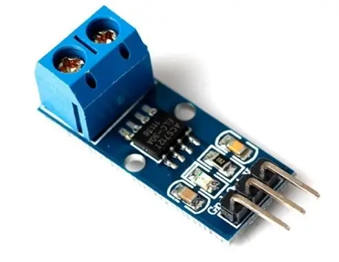
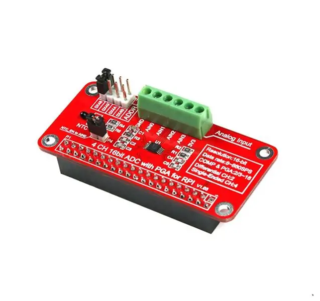
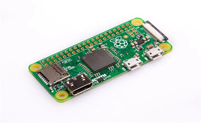
Per realizzare questo progetto utilizzeremo:
- 1 Raspberry Pi Zero
- 1 sensore di corrente AS712 (20A)
- 1 ADC 16bit I2C ADS1555
- 1 sensore RFID RC522
- 1 relè 5V
- Convertitore 1AC/DC 5V/2A ECL10US05-E di Farnell
- 1 presa elettrica
Passaggio 2: cablaggio
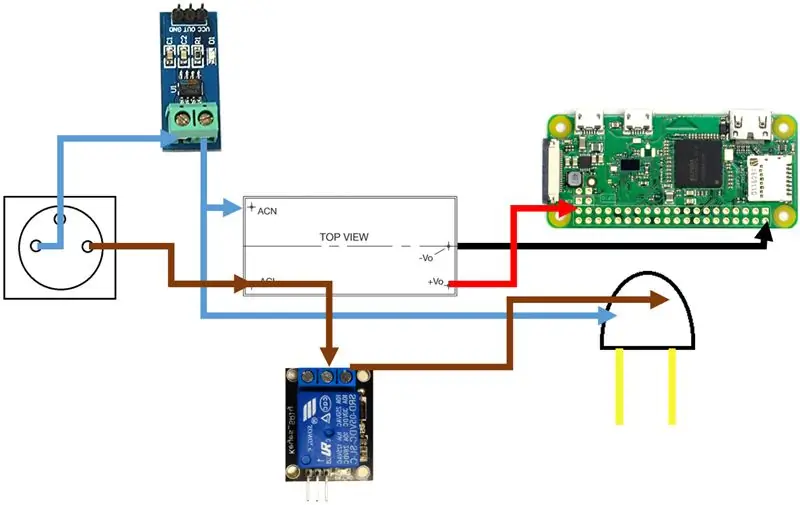
Dobbiamo collegare tutto insieme come mostrato in figura, attenzione alla corrente erogata dal Raspberry Pi.
Cablaggio di comando:
- Alimentazione 3v3 - Relè 5V Vcc/Sensore di corrente Vcc/RFID Vcc/ADC Vcc
- Alimentazione 5v - Convertitore AC/DC 5v
- Massa - Relè 5V GND/Sensore di corrente GND/AC/DC converter GND/RFID GND/ADC input e output GND
- BCM 2 - ADC SDA
- BCM 3 - ADC SCL
- BCM 4 - ADC CLK
- BCM 6 - RFID SDA
- BCM 9 - RFID MISO
- BCM 10 - RFID MOSI
- BCM 11 - RFID SCK
- BCM 17 - Relè 5V IN
- BCM 24 - Ripristino RFID
- BCM 25 - RFID RST
Passaggio 3: codice
Questo codice funziona come segue:
Il sensore RFID attende un tag e lo scrive nel Terminale. Quindi il sensore di corrente misura la quantità di corrente alternata consumata e visualizza nel terminale la potenza istantanea ogni 100 misure. Grazie a ciò, possiamo ottenere la quantità di kWh.
socket di importazione, json
import sys from threading import Thread from pirc522 import RFID import RPi. GPIO as GPIO ## Import libreria GPIO import signal import time import Adafruit_ADS1x15 GPIO.setmode(GPIO. BOARD) GPIO.setup(11, GPIO. OUT) GPIO.output(11, True) rdr = RFID() util = rdr.util() util.debug = True TCP_IP = '172.31.29.215' TCP_PORT = 5000 BUFFER_SIZE = 1024 adc = Adafruit_ADS1x15. ADS1115() def end_read(segnale, frame): esecuzione globale print("\nCtrl+C catturato, fine lettura.") run = False rdr.cleanup() sys.exit() signal.signal(signal. SIGINT, end_read) def loopRead(s): DemandeTag=1 DemandeMesure=0 bol = True while (bol): if DemandeTag==1: tag() DemandeTag=0 DemandeMesure=1 if DemandeMesure==1: Mesure2() try: data = s.recv(BUFFER_SIZE) if not data: break print data dataJSON = json.loads(data) if "message" in dataJSON: print dataJSON['message'] if dataJSON['message'] == "exit": print('Exit demande') GPIO.output(11, GPIO. HIGH) DemandeTag=0 DemandeMesure=0 bol = False se dataJSON['message'] == "on": GPIO.output(11, GPIO. LOW) DemandeMesure=1 DemandeTag=1 if dataJSON['message'] == "off": GPIO.output(11, GPIO. HIGH) DemandeTag=1 message='' tranne Eccezione come e: continue s.close() def tag(): rdr.wait_for_tag() (error, data) = rdr.request() time.sleep(0.25) (error, uid) = rdr.anticoll() ID=str(uid[0])+'.'+str(uid[1])+'.'+str(uid[2])+'.'+str(uid[3]) print("UID lettura tessera: "+ID) GPIO.output(11, GPIO. LOW) def Mesure(): mesure_voltage = 0 Nbre_mesure=100 i = 0 while i def Mesure2(): mesure_voltage = 0 Nbre_mesure=200 max_voltage=0 min_voltage=32768 mVparAmp = 100 Puissance=0 i = 0 readValue=0 while imax_voltage: max_voltage=readValue if readValue def Mesure3(): print(str(adc.read_adc(0, gain=1))) if _name_ == "_main_": s = socket.socket(socket. AF_INET, socket. SOCK_STREAM) #s.connect((TCP_IP, TCP_PORT)) #s.setblocking(0) loopRead(s)
Passaggio 4: la scatola
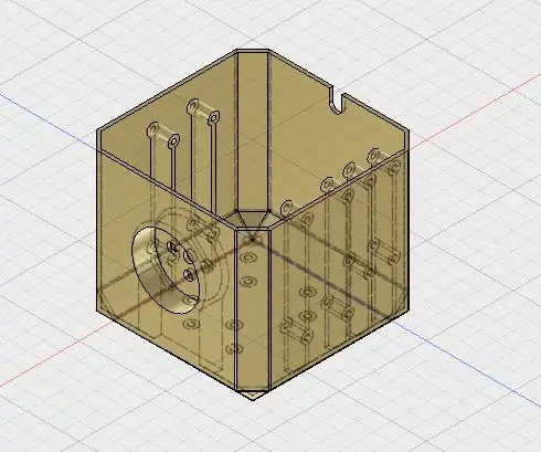
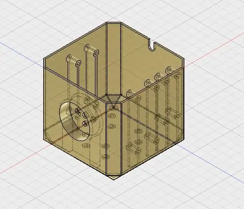
Per rendere più compatta tutta l'elettronica, abbiamo progettato una scatola che conterrà tutto al suo interno. Per avvitare tutto utilizzeremo viti M3.
Consigliato:
Come realizzare un'antenna doppia biQuade 4G LTE Semplici passaggi: 3 passaggi

Come realizzare un'antenna doppia biQuade 4G LTE Semplici passaggi: La maggior parte delle volte che ho affrontato, non ho una buona potenza del segnale per i miei lavori quotidiani. Così. Cerco e provo diversi tipi di antenna ma non funziona. Dopo aver perso tempo ho trovato un'antenna che spero di realizzare e testare, perché è principio costruttivo non
Rilevamento del volto su Raspberry Pi 4B in 3 passaggi: 3 passaggi

Rilevamento del volto su Raspberry Pi 4B in 3 passaggi: In questo Instructable eseguiremo il rilevamento del volto su Raspberry Pi 4 con Shunya O/S utilizzando la libreria Shunyaface. Shunyaface è una libreria di riconoscimento/rilevamento facciale. Il progetto mira a raggiungere la massima velocità di rilevamento e riconoscimento con
Specchio per il trucco fai-da-te in semplici passaggi (usando le strisce luminose a LED): 4 passaggi

Specchio per il trucco fai-da-te in semplici passaggi (usando le strisce luminose a LED): in questo post, ho realizzato uno specchio per il trucco fai-da-te con l'aiuto delle strisce LED. Sono davvero fantastici e devi provarli anche tu
Gioca a Doom sul tuo iPod in 5 semplici passaggi!: 5 passaggi
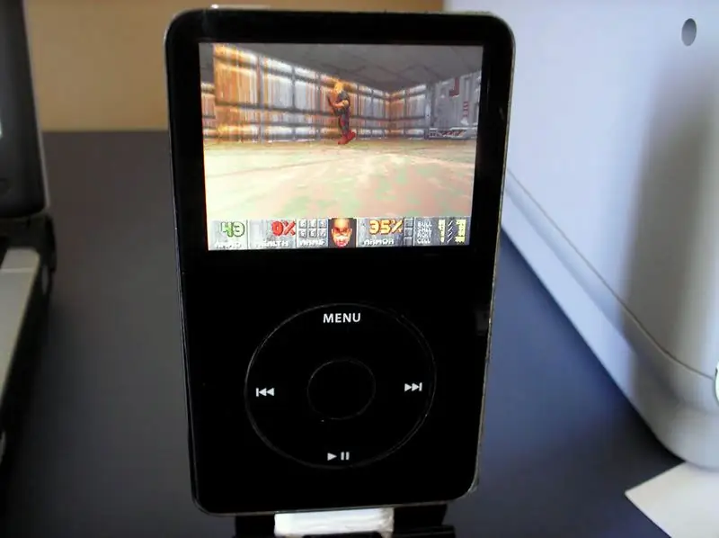
Gioca a Doom sul tuo iPod in 5 semplici passaggi!: una guida passo passo su come eseguire il dual-boot di Rockbox sul tuo iPod per giocare a Doom e a dozzine di altri giochi. È qualcosa di veramente facile da fare, ma molte persone rimangono stupite quando mi vedono giocare a doom sul mio iPod e si confondono con le istruzioni
Come installare plugin in WordPress in 3 passaggi: 3 passaggi

Come installare plugin in WordPress in 3 passaggi: In questo tutorial ti mostrerò i passaggi essenziali per installare il plugin wordpress sul tuo sito web. Fondamentalmente puoi installare i plugin in due modi diversi. Il primo metodo è tramite ftp o tramite cpanel. Ma non lo elencherò perché è davvero completo
